m (→Pipe header: formatting) |
Kwjcool321 (talk | contribs) mNo edit summary |
||
| (5 intermediate revisions by 5 users not shown) | |||
| Line 1: | Line 1: | ||
| − | {{stub}} |
||
'''Manifold''', a.k.a. in-line [[Splitter|splitting]] / [[Merger|merging]] refers to a type building style where splitters or mergers are aligned in a straight line, usually parallel to the arrangement of buildings. This allows for compact building space and easier expansion. |
'''Manifold''', a.k.a. in-line [[Splitter|splitting]] / [[Merger|merging]] refers to a type building style where splitters or mergers are aligned in a straight line, usually parallel to the arrangement of buildings. This allows for compact building space and easier expansion. |
||
| Line 5: | Line 4: | ||
== Conveyor Belt manifold == |
== Conveyor Belt manifold == |
||
| − | * Due to |
+ | * Due to the mechanisms of [[Splitter]]s, the machines closer to the source will fill up faster and start running, the machines at the end of the line will have to wait for the resource to fill up the preceding machines first before their input resource is prioritized. The this also applies to mergers in the same configuration on the output side of the machines. |
| − | * If one |
+ | * If one or more outputs of a splitter are saturated with items, all of the remaining items will automatically overflow to the remaining connected outputs. |
| − | * |
+ | * Given enough time, all machines in a manifold will run at 100%, provided the input and output item rates are sufficient and the item speed is not limited by conveyor throughput. |
| ⚫ | |||
| − | * Given enough time, all machines in the manifold will be running at 100%, providing the input and output items rates are sufficient and the item speed is not limited by the conveyor throughput. |
||
| + | |||
| ⚫ | |||
<gallery> |
<gallery> |
||
File:Manifold Schematics.png|A few examples of manifold arrangements. |
File:Manifold Schematics.png|A few examples of manifold arrangements. |
||
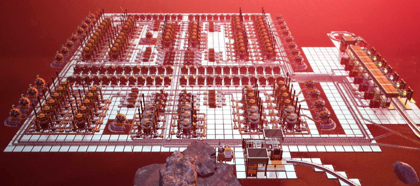
File:Solid Steel Ingot Manifold.png|A Solid Steel Ingot production area in-game. Iron Ores from top left, Coal from bottom left, Two belts of Steel Ingots exit at the bottom. |
File:Solid Steel Ingot Manifold.png|A Solid Steel Ingot production area in-game. Iron Ores from top left, Coal from bottom left, Two belts of Steel Ingots exit at the bottom. |
||
| − | File:Square Manifold Example.png|A more square alternative to manifolds involving constructors or smelters, trading length for width. Take note this may |
+ | File:Square Manifold Example.png|A more square alternative to manifolds involving constructors or smelters, trading length for width. Take note this may require a slightly larger area per machine. |
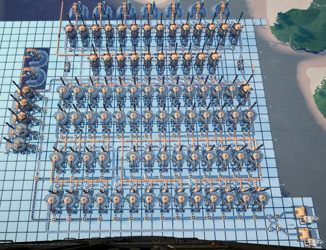
| + | File:Ingame setup featuring manifolds.webp|A large-scale setup of Heavy Modular Frames featuring manifold fill. |
||
</gallery> |
</gallery> |
||
| Line 22: | Line 22: | ||
* The total fluid input must be equal to the total fluid output (conservation of fluid flow). |
* The total fluid input must be equal to the total fluid output (conservation of fluid flow). |
||
* No single segment of pipeline can exceed the flow rate of 300 {{m3pm}} (Mk.1) or 600 {{m3pm}} (Mk.2). |
* No single segment of pipeline can exceed the flow rate of 300 {{m3pm}} (Mk.1) or 600 {{m3pm}} (Mk.2). |
||
| − | * Pipelines are bi-directional, so any fluctuation in fluid amount or flow rate will be auto-balanced by themselves. That means you won't have to worry about the fluid direction in individual pipe segment, only need to consider the overall flow. |
+ | * Pipelines are bi-directional, so any fluctuation in fluid amount or flow rate will be auto-balanced by themselves. That means you won't have to worry about the fluid direction in the individual pipe segment, only need to consider the overall flow. |
<gallery> |
<gallery> |
||
| − | File:Coal Generator Schematic.png|Optimum setup with |
+ | File:Coal Generator Schematic.png|Optimum setup with eight [[Coal Generator]]s and three [[Water Extractor]]s. Make sure the middle Water Extractor is in between the 4th and 5th Coal Generator or it won't work. |
File:Coal generator pipe analysis.png|The flow rate analysis of the previous diagram, which is a 'pipe header' design. Take note no segment of the pipe contains more than 300 {{m3pm}} of flow. |
File:Coal generator pipe analysis.png|The flow rate analysis of the previous diagram, which is a 'pipe header' design. Take note no segment of the pipe contains more than 300 {{m3pm}} of flow. |
||
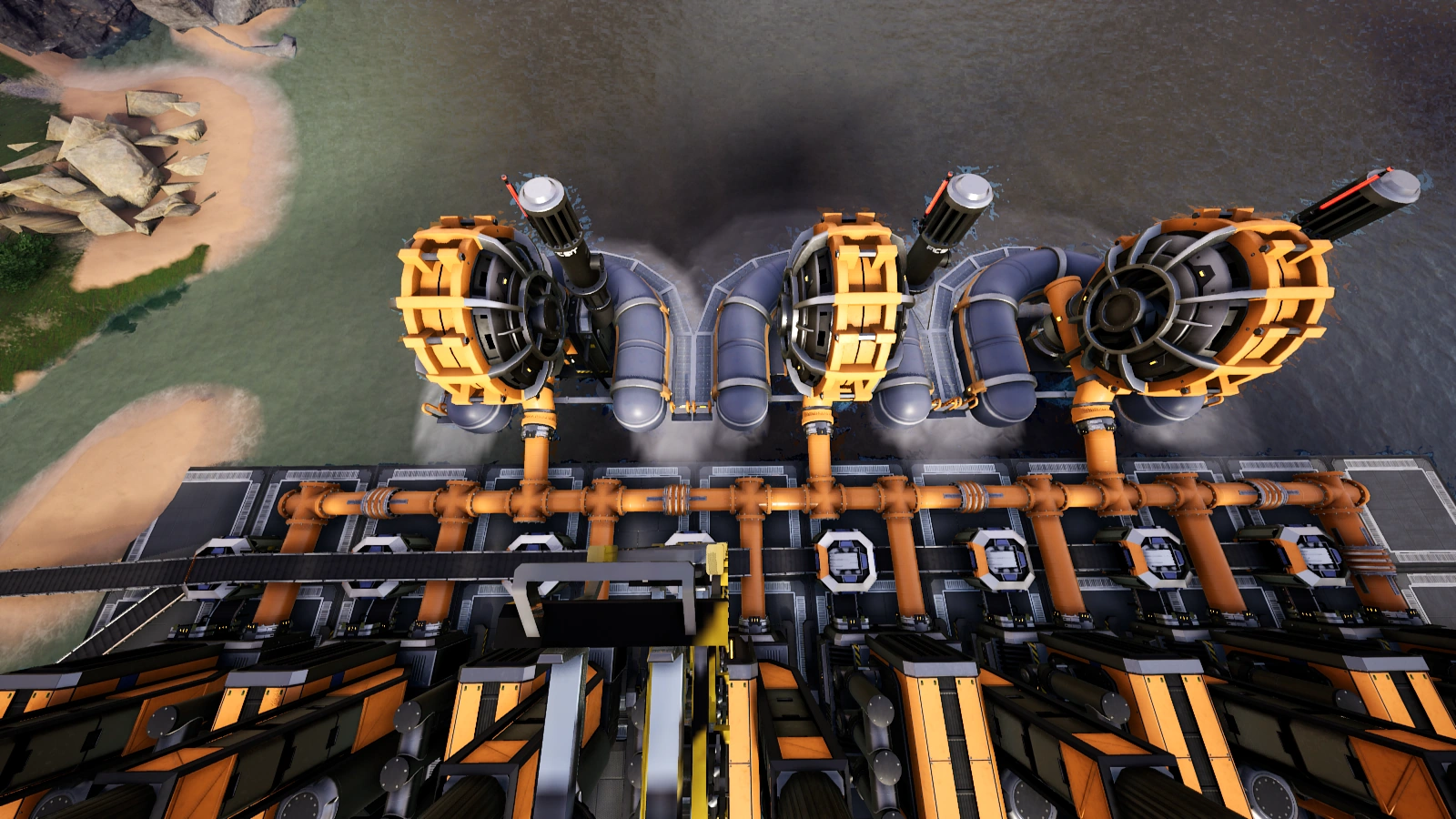
| − | File:Coal power Water Extractor.png|Top view of |
+ | File:Coal power Water Extractor.png|Top view of three Extractors to eight Generators setup, using a common pipeline and two Mk.1 belts, each feed into four generators. The two Mk.1 [[belt]]s can be merged to a single Mk.2 belt. |
File:Plastic production.png|Pipe header design is commonly used in [[Oil]]-related setup. |
File:Plastic production.png|Pipe header design is commonly used in [[Oil]]-related setup. |
||
File:Aluminum production.png|Pipe header in [[Aluminum]] production. |
File:Aluminum production.png|Pipe header in [[Aluminum]] production. |
||
| Line 33: | Line 33: | ||
== External links == |
== External links == |
||
| − | * https://satisfactory.greeny.dev/machine-fill A calculator for calculating machine fill time in a manifold |
+ | * [https://satisfactory.greeny.dev/machine-fill satisfactory.greeny.dev - A calculator for calculating machine fill time in a manifold] |
| − | * https://www.reddit.com/r/SatisfactoryGame/comments/btexf7/satisfactory_saturdays_2_balancers_vs_manifolds/ Detailed article about balancers vs manifolds |
+ | * [https://www.reddit.com/r/SatisfactoryGame/comments/btexf7/satisfactory_saturdays_2_balancers_vs_manifolds/ Reddit - /r/SatisfactoryGame/ - Detailed article about balancers vs manifolds] |
| − | {{ |
+ | {{PioneerNav}} |
[[Category:Tutorials]] |
[[Category:Tutorials]] |
||
Revision as of 15:58, 22 April 2021
Manifold, a.k.a. in-line splitting / merging refers to a type building style where splitters or mergers are aligned in a straight line, usually parallel to the arrangement of buildings. This allows for compact building space and easier expansion.
It is the opposite fill method to the balancer.
Conveyor Belt manifold
- Due to the mechanisms of Splitters, the machines closer to the source will fill up faster and start running, the machines at the end of the line will have to wait for the resource to fill up the preceding machines first before their input resource is prioritized. The this also applies to mergers in the same configuration on the output side of the machines.
- If one or more outputs of a splitter are saturated with items, all of the remaining items will automatically overflow to the remaining connected outputs.
- Given enough time, all machines in a manifold will run at 100%, provided the input and output item rates are sufficient and the item speed is not limited by conveyor throughput.
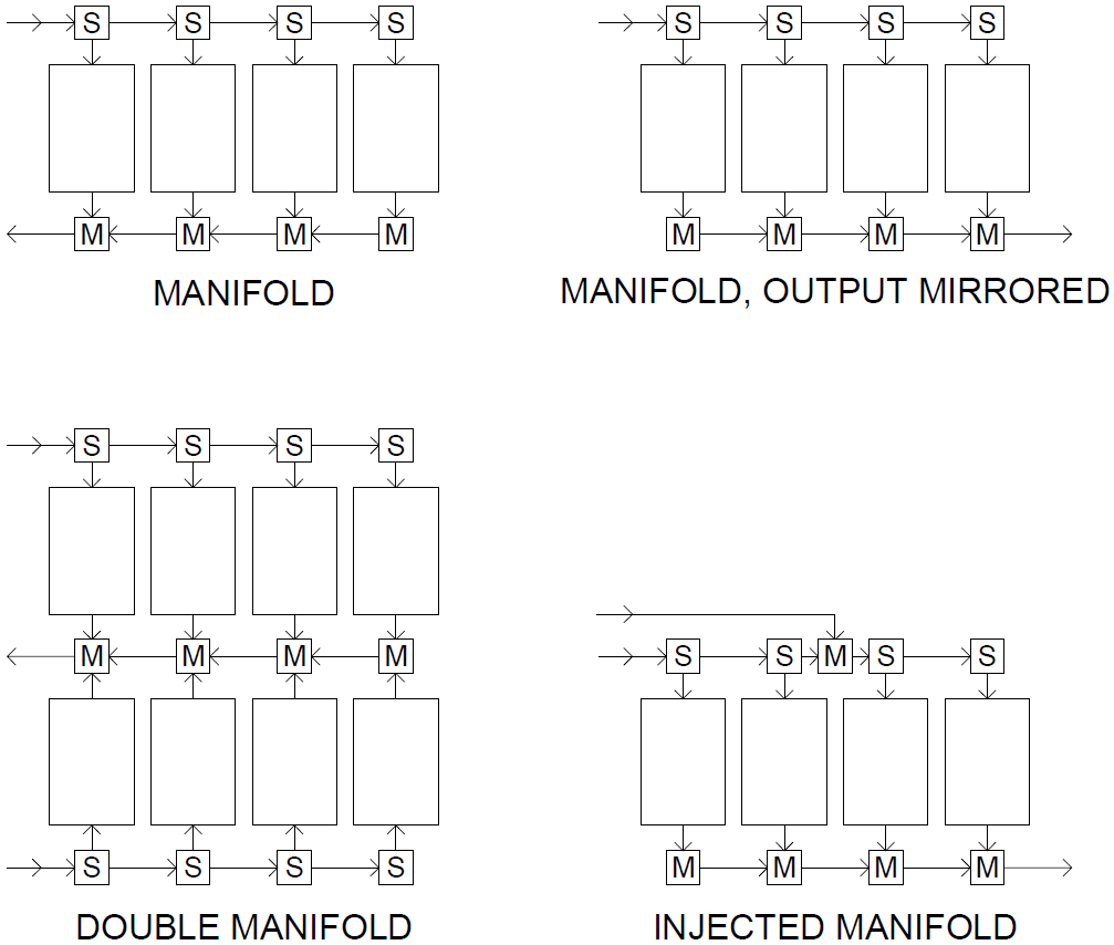
- If conveyor throughput is a limiting factor, consider using an 'injected manifold', where supplementary supply belt/s are merged at places lacking feed throughput.

A few examples of manifold arrangements.

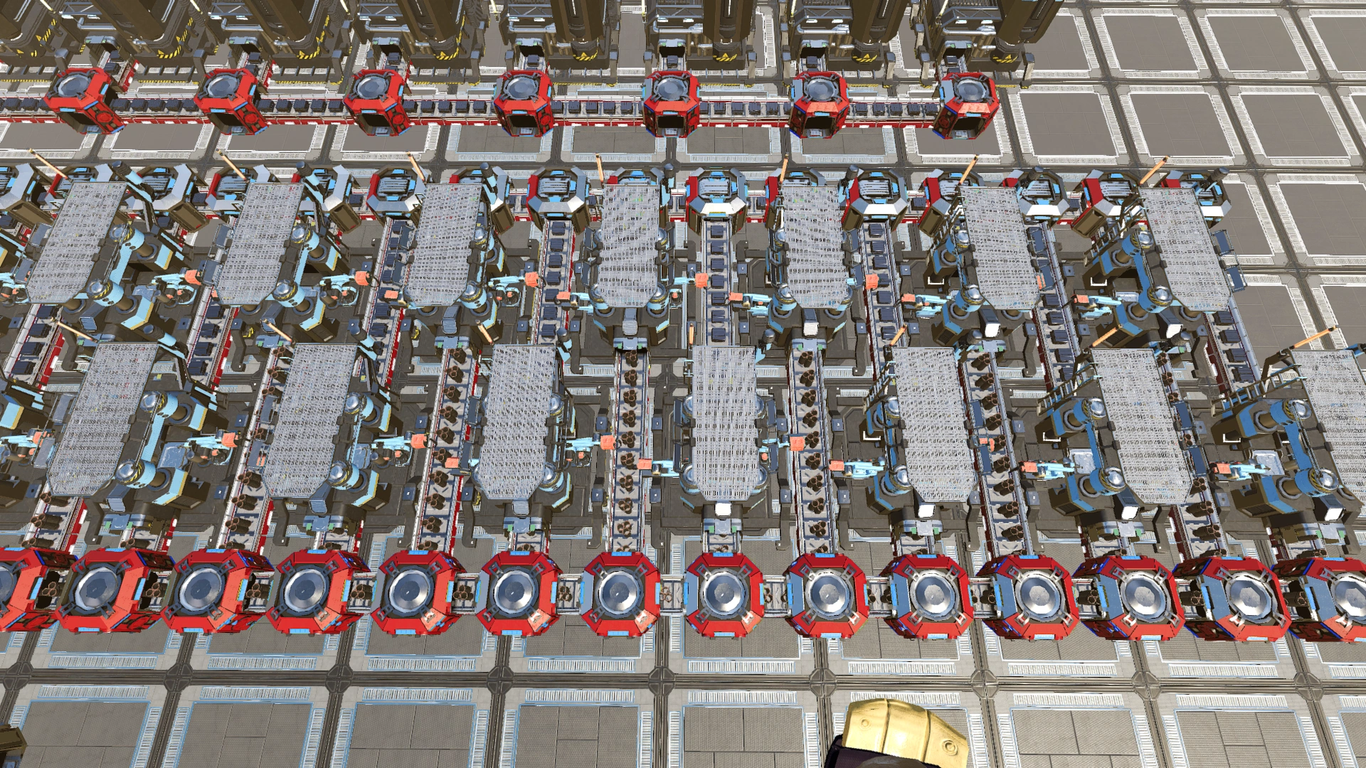
A Solid Steel Ingot production area in-game. Iron Ores from top left, Coal from bottom left, Two belts of Steel Ingots exit at the bottom.

A more square alternative to manifolds involving constructors or smelters, trading length for width. Take note this may require a slightly larger area per machine.

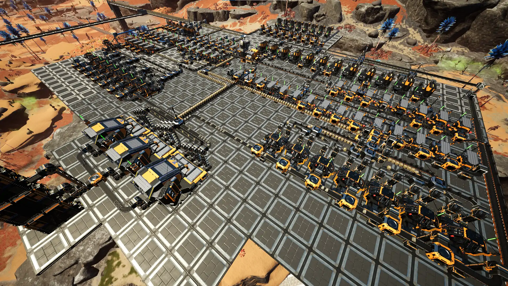
A large-scale setup of Heavy Modular Frames featuring manifold fill.
Pipe header
A pipeline manifold, a.k.a pipe header, is a kind of arrangement where a 'main' pipe is connected to a series of secondary pipes. It can serve either as a fluid distributor or a fluid collector. This can be constructed by chaining a series of Pipeline Junction Crosses connected with Pipelines.
A pipe header works with the following principles:
- The total fluid input must be equal to the total fluid output (conservation of fluid flow).
- No single segment of pipeline can exceed the flow rate of 300 m3/min (Mk.1) or 600 m3/min (Mk.2).
- Pipelines are bi-directional, so any fluctuation in fluid amount or flow rate will be auto-balanced by themselves. That means you won't have to worry about the fluid direction in the individual pipe segment, only need to consider the overall flow.
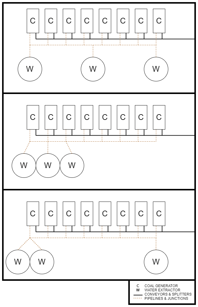
Optimum setup with eight Coal Generators and three Water Extractors. Make sure the middle Water Extractor is in between the 4th and 5th Coal Generator or it won't work.
The flow rate analysis of the previous diagram, which is a 'pipe header' design. Take note no segment of the pipe contains more than 300 m3/min of flow.
Top view of three Extractors to eight Generators setup, using a common pipeline and two Mk.1 belts, each feed into four generators. The two Mk.1 belts can be merged to a single Mk.2 belt.
Pipe header design is commonly used in Oil-related setup.
Pipe header in Aluminum production.
External links
- satisfactory.greeny.dev - A calculator for calculating machine fill time in a manifold
- Reddit - /r/SatisfactoryGame/ - Detailed article about balancers vs manifolds
| |||||||||||||||||||||||||||||